武田机电

LION电容式传感器
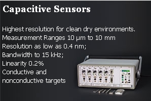
Lion Precision Capacitive Sensors - An Overview This single page will give you an overview of capacitive sensor operation, application, theory, and resources. Links to more detailed information are also provided. Or you can go directly to one of these pages: Capacitive Products Selector Capacitive Literature/Manual Download Detailed Capacitive Theory Comparison of Capacitive and Eddy-Current Sensors 2010 Survey Response "Lion Precision quoted quickly, efficiently and professionally. The competition had a 4 week lead time to quote, and 8 weeks delivery in product. Lion wins hands down!" Capacitive sensors are noncontact devices capable of high-resolution measurement of the position and/or change of position of any conductive target. The nanometer resolution of high-performance capacitive sensors makes them indispensable in today's nanotechnology world. They can also be used to measure the position or other properties of nonconductive targets. Below you will find: Basic Theory, High-Performance Capacitive Sensors, Capacitive Sensor Advantages, Applications, and Products Overview. Basic Theory Capacitive sensors use the electrical property of "capacitance" to make measurements. Capacitance is a property that exists between any two conductive surfaces within some reasonable proximity. Changes in the distance between the surfaces changes the capacitance. It is this change of capacitance that capacitive sensors use to indicate changes in position of a target. High-performance displacement sensors use small sensing surfaces and as result are positioned close to the targets (0.25-2 mm). For a thorough explanation of how capacitive sensing works, please visit the Capacitive Sensor Theory page. High-Performance Sensors A high performance capacitive sensor system It is important to distinguish between "high-performance" capacitive sensors and inexpensive capacitive sensors. Simple capacitive sensors, such as those used in inexpensive proximity switches or elevator touch switches, are simple devices and in their most basic form could be designed in a high school electronics class. Proximity type sensors are tremendously useful in automation applications and many commercially available models are well made, but they are not suited to precision metrology applications. In contrast, capacitive sensors for use in precision displacement measurement and metrology applications use complex electronic designs to execute complex mathematical algorithms. Unlike inexpensive sensors, these high-performance sensors have outputs which are very linear, stable with temperature, and able to resolve incredibly small changes in capacitance resulting in high resolution measurements of less than one nanometer. Capacitive Sensor Advantages Compared to other noncontact sensing technologies such as optical, laser, eddy-current, and inductive, high-performance capacitive sensors have some distinct advantages. Higher resolutions including subnanometer resolutions Not sensitive to material changes: Capacitive sensors respond equally to all conductors Less expensive and much smaller than laser interferometers. Capacitive sensors are not good choice in these conditions: Dirty or wet environment (eddy-current sensors are ideal) Large gap between sensor and target is required (optical and laser are better) Visit the Eddy-Current vs. Capacitive Sensors page for a more detailed comparison between the two technologies. Applications Capacitive sensors are useful in any application requiring the measurement or monitoring of the position of a conductive target. Position Measurement/Sensing Capacitive sensors are basically position measuring devices. Their outputs always indicate the size of the gap between the sensor's sensing surface and the target. When the probe is stationary, any changes in the output are directly interpreted as changes in position of the target. This is useful in: Automation requiring precise location Semiconductor processing Final assembly of precision equipment such as disk drives Precision stage positioning Dynamic Motion Measuring the dynamics of a continuously moving target, such as a rotating spindle or vibrating element, requires some form of noncontact measurement. Capacitive sensors are ideal when the environment is clean and the motions are small, requiring high-resolution measurements. Lion Precision capacitive sensors also have high frequency response (15 kHz) to accommodate high-speed motion. Precision machine tool spindles Disk drive spindles High-speed drill spindles Ultrasonic welders Vibration measurements Thickness Measurement Measuring material thickness in a noncontact fashion is a common application for capacitive sensors. The most useful application is a two-channel differential system in which a separate sensor is used for each side of the piece being measured. Details on thickness measurements with capacitive sensors is available in the Conductive Material Thickness Measurement with Capacitive Sensors Application Note. Capacitive sensor technology is used for thickness measurement in these applications: Silicon wafer thickness Brake rotor thickness Disk drive platter thickness Nonconductive Thickness Capacitive sensors are sensitive to nonconductive materials which are placed between the probe's sensing area and a grounded back target. If the gap between the sensor and the back target is stable, changes in the sensor output are indicative of changes in thickness, density, or composition of the material in the gap. This is used for measurements in these applications: Label positioning during application Label counting Glue detection Glue thickness Assembly testing The glue sensing application is detailed in the Sensing Glue on Paper with Capacitive Sensors Application Note. Label sensor products and technical detail are available at www.labelsensors.com. For details on the measurement of nonconductive targets, please see the more detailed Capacitive Sensor Theory page. Assembly testing Capacitive sensors have a much higher sensitivity to conductors than to nonconductors. Therefore, they can be used to detect the presence/absence of metallic subassemblies in completed assemblies. An example is a connector assembly requiring an internal metallic snap ring which is not visible in the final assembly. Online capacitive sensing can detect the defective part and signal the system to remove it from the line. Capacitive Sensor Products Overview High-perfromance capacitive sensors generally consist of an electronics module and probe which is connected to the module by a cable. These systems are available in different configurations and price points. The Elite Series capacitive sensors feature a modular design in which single or multiple channels of electronics modules are enclosed in a modular rack. All of the channels are synchronized and a meter/display can be added to the system. Each capacitive sensor module has a "calibrated range" display and coarse and fine zero adjustments for adjusting the DC level of the sensor output. The Elite Series are the highest performing capacitive sensors. The Compact Driver contains from one to six capacitive sensor channels in a small box with no user controls. Separate connectors are provided for power in and sensor channel outputs. Connectors are also provided for the probes. This system is ideal for OEM applications in which the capacitive sensor system is embedded within a larger system. The lack of user adjustments prevents inaccurate readings resulting from "operator error." The Process Monitor (PM755) is a lower cost capacitive sensor. The output from this sensor is repeatable but not linear. The system is used in servo "zero-seeking" systems where the capacitive sensor outputs are used to drive a system to a known good condition rather than measuring the extent to which the system is out of tolerance. It is also used where a threshold voltage is established at which some conditional action is initiated. For more detail on capacitive sensor products, visit the Capacitive Sensor Products page. For more detail on the operation and theory of capacitive sensors, visit the Capacitive Sensor Theory page
Comparing Capacitive and Eddy-Current Sensors General Sensor TechNote LT05-0011 Copyright ? 2009 Lion Precision. Quick Comparison Table (below) Capacitive Sensor Products Eddy-Current Sensor Products Introduction Noncontact sensors using capacitive and eddy-current technologies each represent a unique blend of advantages and disadvantages for a variety of applications. This comparison of the two technologies’ strengths will help you select the best technology for your application. Figure 1. Capacitive Probe Construction Figure 2. Eddy-Current Probe Construction Sensor Construction Understanding the difference between capacitive and eddy-current sensors begins by looking at how they are constructed. At the center of a capacitive probe is the sensing element. This piece of stainless steel generates the electric field which is used to sense the distance to the target. Separated from the sensing element by an insulating layer is the guard ring, also made of stainless steel. The guard ring surrounds the sensing element and focuses the electric field toward the target. A few electronic components are connected to the sensing element and guard ring. All of these internal assemblies are surrounded by an insulating layer and encased in a stainless steel housing. The housing is connected to the grounded shield of the cable (Figure 1). The primary functional piece of an eddy-current probe is the sensing coil. This is a coil of wire near the end of the probe. Alternating current is passed through the coil which creates an alternating magnetic field; this field is used to sense the distance to the target. The coil is encapsulated in plastic and epoxy and installed in a stainless steel housing. Because the magnetic field of an eddy-current sensor is not as easily focused as the electric field of a capacitive sensor, the epoxy covered coil extends from the steel housing to allow the full sensing field to engage the target (Figure 2). Spot Size, Target Size, and Range Figure 3. Capacitive probe spot size The sensing field of a noncontact sensor’s probe engages the target over a certain area. The size of this area is called the spot size. The target must be larger than the spot size or special calibration will be required.Spot size is always proportional to the diameter of the probe. The ratio between probe diameter and spot size is significantly different for capacitive and eddy-current sensors. These different spot sizes result in different minimum target sizes. Capacitive sensors use an electric field for sensing. This field is focused by a guard ring on the probe resulting in a spot size about 30% larger than the sensing element diameter (Figure 3). A typical ratio of sensing range to the sensing element diameter is 1:8. This means that for every unit of range, the sensing element diameter must be eight times larger. For example, a sensing range of 500μm requires a sensing element diameter of 4000μm (4mm). This ratio is for typical calibrations. High resolution and extended range calibrations will alter this ratio. Figure 4. Eddy-Current probe spot size Eddy-current sensors use magnetic fields that completely surround the end of the probe. This creates a comparatively large sensing field resulting in a spot size approximately three times the probe’s sensing coil diameter (Figure 4). For eddy-current sensors, the ratio of the sensing range to the sensing coil diameter is 1:3. This means that for every unit of range, the coil diameter must be three times larger. In this case, the same 500μm sensing range only requires a 1500μm (1.5mm) diameter eddy-current sensor. When selecting a sensing technology, consider target size. Smaller targets may require capacitive sensing. If your target must be smaller than the sensor’s spot size, special calibration may be able to compensate for the inherent measurement errors. Sensing Technique Figure 5. Capacitive probe guarding Capacitive and eddy-current sensors use different techniques to determine the position of the target. Capacitive sensors used for precision displacement measurement use a high-frequency electric field, usually between between 500kHz and 1MHz. The electric field is emitted from the surfaces of the sensing element. To focus the sensing field on the target, a guard ring creates a separate but identical electric field which isolates the sensing element’s field from everything but the target (Figure 5). The amount of current flow in the electric field is determined in part by the capacitance between the sensing element and the target surface. Because the target and sensing element sizes are constant, the capacitance is determined by the distance between the probe and the target, assuming the material in the gap does not change. Changes in the distance between the probe and the target change the capacitance which in turn changes the current flow in the sensing element. The sensor electronics produce a calibrated output voltage which is proportional to the magnitude of this current flow, resulting in an indication of the target position. Figure 6 Magnetic field induces eddy current in conductive target Rather than electric fields, eddy-current sensors use magnetic fields to sense the distance to the target. Sensing begins by passing alternating current through the sensing coil. This creates an alternating magnetic field around the coil. When this alternating magnetic field interacts with the conductive target, it induces a current in the target material called an eddy current. This eddy current produces its own magnetic field which oppose the sensing coil’s field (Figure 6). The sensor is designed to create a constant magnetic field around the sensing coil. As the eddy currents in the target oppose the sensing field, the sensor will increase the current to the sensing coil to maintain the original magnetic field. As the target changes its distance from the probe, the amount of current required to maintain the magnetic field also changes. The sensing coil current is processed to create the output voltage which is then an indication of the position of the target relative to the probe. Error Sources Eddy-current sensors use changes in a magnetic field to determine the distance to the target; capacitive sensors use changes in capacitance. There are factors other than the distance to the target that can also change a magnetic field or capacitance. These factors represent potential error sources in your application. Fortunately, in most cases these error sources are different for the two technologies. Understanding the presence and magnitude of these error sources in your application will help you choose the best sensing technology. The remainder of this article will explain these error sources so that you can make the best choice for your application and get the best possible results. Gap Contamination In some applications, the gap between the sensor and target can become contaminated by dust, liquids such as coolant, and other materials which are not part of the intended measurement. How the sensor reacts to the presence of these contaminants is a critical factor in choosing capacitive or eddy-current sensors. Figure 7 Gap contamination creates change in gap dielectric Capacitive sensors assume that changes in capacitance between the sensor and the target are a result of a change in distance between them. Another factor that affects capacitance is the dielectric constant (ε) of the material in the gap between the target and sensor. The dielectric constant of air is slightly greater than one; if another material, with a different dielectric constant, enters the sensor/target gap, the capacitance will increase, and the sensor will erroneously indicate that the target has moved closer to the sensor (Figure 7). The higher the dielectric constant of the contaminant, the greater the effect on the sensor. Oil has a dielectric constant between 8 and 12. Water has a very high dielectric constant of 80. Because of the sensitivity to the dielectric constant of the material between the sensor and the target, capacitive displacement sensors must be used in a clean environment when measuring target position. The dielectric sensitivity of capacitive sensors can be exploited for use in sensing the thickness or density of nonconductive materials. For more information on this type of application, please refer to our Capacitive Sensor Theory TechNote. Unlike capacitive sensors, eddy-current sensors use magnetic fields for sensing. Magnetic fields are not affected by nonconductive contaminants such as dust, water, and oil. As these contaminants enter the sensing area between an eddy-current sensor and the target, the sensor’s output is not affected. For this reason, an eddy-current sensor is the best choice when the application involves a dirty or hostile environment. Lion Precision eddy-current probes are rated at IP67 and can even be used completely immersed in non-corrosive liquid. Target Thickness Capacitive and eddy-current sensors have different requirements for target thickness. The electric field of a capacitive sensor engages only the surface of the target with no significant penetration into the material. Because of this, capacitive sensors are not affected by material thickness. The magnetic field of an eddy-current sensor must penetrate the surface of the target in order to induce eddy currents in the material. If the material is too thin, smaller eddy currents in the target produce a weaker magnetic field. This results in the sensor having reduced sensitivity and a smaller signal to noise ratio. The depth of penetration of the sensor’s magnetic field is dependent on the material and the frequency of the sensor’s oscillating magnetic field. Lion Precision eddy-current sensors typically use a frequency of 1-2MHz. Table 1 shows minimum thicknesses for some common materials. More detail can be found on the Minimum Recommended Target Thickness TechNote. Target Materials and Rotating Targets Capacitive and eddy-current sensors respond very differently to differences in target material. The magnetic field of an eddy-current sensor penetrates the target and induces an eddy current in the material which creates a magnetic field that opposes the field from the probe. The strength of the eddy current and the resulting magnetic field depend on the permeability and resistivity of the material. These properties vary between different materials. They can also be changed by different processing techniques such as heat treating or annealing. For example, two otherwise identical pieces of aluminum that were processed differently may have different magnetic properties. Between different nonmagnetic materials such as aluminum and titanium the variance of permeability and resistivity can be small, but a high performance eddy-current sensor calibrated for one nonmagnetic material will still produce errors when used with a different nonmagnetic material. The differences between nonmagnetic materials like aluminum and titanium and magnetic materials such as iron or steel are enormous. While the relative permeability of aluminum and titanium are approximately one, the relative permeability of iron can be as high as 10,000. Eddy-current sensors calibrated for nonmagnetic materials are not likely to function at all when used with magnetic materials. When using eddy-current sensors for precise measurements, it is critical that the sensor be calibrated for the specific material used in the application. The high permeability of magnetic materials such as iron and steel can also cause small eddy-current sensor errors within the same piece of material. Within any imperfect material, there are microscopic cracks and material variations. The material’s permeability changes slightly around these areas. While the changes are relatively small, the extremely high permeability of magnetic materials enables high-resolution eddy-current sensors to detect these changes. This problem is most evident in rotating targets of magnetic materials. Figure 8 Runout plot showing actual runout in blue, and electrical runout from eddy-current sensor in red. An eddy-current sensor can be mounted to measure the runout of a rotating shaft. But even if the shaft is ideal, with absolutely no runout, a high resolution eddy-current sensor will detect a repeatable pattern of changes as the shaft rotates (Figure 8). These changes are a result of small variations in the material. This phenomenon is well known and is called electrical runout. These errors can be very small, often in the micron range. Many shaft runout applications, especially those in hostile environments where eddy-current sensors are the norm, are looking for much larger errors and can therefore tolerate these errors. Other more precise applications will need to use techniques to address these errors or use a different sensing technology such as capacitive sensors. The electric field of a capacitive sensor uses the target as a conductive path to ground. All conductive materials offer this equally well, so capacitive sensors measure all conductive materials the same. Once a capacitive sensor is calibrated, it can be used with any conductive target with no degradation in performance. Because the electric field of a capacitive sensor does not penetrate the material, variations within the material do not affect the measurement. Capacitive sensors do not exhibit the electrical runout phenomenon of eddy-current sensors and can be used with rotating targets of any conductive material without additional error. Eddy-current sensors should be calibrated to the same material as the target in the application and should not be used with rotating magnetic material targets unless the electrical runout errors are acceptable in the application. Capacitive sensors, once calibrated, can be used with any conductive material with no material related errors, and they work well with rotating targets. Environmental Parameters: Temperature and Vacuum Because of differences in the sensing physics and the associated differences in driver electronics, capacitive and eddy-current sensors have different probe operating temperature ranges and vacuum compatibility. Lion Precision capacitive and eddy-current probes have different operating temperature ranges. Eddy-current probes, because of their tolerance of hostile environments have a greater temperature range. Standard eddy-current probes, which use polyurethane cables, have an operating range from -25 to +125°C. High temperature probes, which use teflon FEP cables, have an operating range of -25 to +200°C. Capacitive probes, which are affected by condensation, only have an operating range of +4 to +50 °C. The driver electronics for both sensing technologies have an operating range of +4 to +50°C. Capacitive and eddy-current probes can both be used in vacuum applications. Materials in the probes are selected for structural stability and minimized outgassing under vacuum. Vacuum compatible probes are subjected to an extra cleaning process and special packaging to remove foreign materials that may threaten a delicate vacuum environment. Many vacuum applications require precise temperature control. The probe’s power consumption, with its associated contribution to temperature change, is where capacitive and eddy-current technologies differ. A capacitive probe has extremely small current flow and power consumption. A typical capacitive probe consumes less than 40μW of power, contributing very little heat to the vacuum chamber. The power consumption in an eddy-current probe can vary from 40μW to as high as 1mW. At these higher powers, the eddy-current probe will contribute more heat to the vacuum chamber and could disturb high-precision vacuum environments. The power consumption in an eddy-current probe is dependent on many factors; probe size alone is not a good predictor of power consumption. Each eddy-current sensor’s power consumption must be assessed individually. Either capacitive or eddy-current sensors can work well in vacuum environments. In temperature sensitive vacuums, eddy-current sensors may contribute too much heat for the application. In these applications, capacitive sensors will be a better choice. Probe Mounting Figure 9. Interference occurs when eddy-current probes are mounted near each other. Because of differences in the shape and reactive nature of the sensing fields of capacitive and eddy-current sensors, the technologies have different probe mounting requirements. Eddy-current probes produce comparatively large magnetic fields. The field diameter is at least three times larger than the probe diameter and greater than three diameters for large probes. If multiple probes are mounted close together, the magnetic fields will interact (Figure 9). This interaction will create errors in the sensor outputs. If this type of mounting is unavoidable, sensors based on digital technology such as the ECL202 can be specially calibrated to reduce or eliminate the interference from adjacent probes. Figure 10. Mounting hardware can interfere with eddy-current probe magnetic field. The magnetic field from an eddy-current probe also extends about one and a half diameters behind the probe. Any metallic objects in this area, usually mounting hardware, will interact with the field and affect the sensor output (Figure 10). If nearby mounting hardware is unavoidable, sensors can be calibrated with the mounting hardware in place which will compensate for the effect of the hardware. The electric fields of capacitive probes are only emitted from the front surface of the probe. The field has a slightly conical shape resulting in a spot size about 30% larger than the sensing area diameter. Nearby mounting hardware or other objects are rarely in the field area and therefore do not affect the sensor’s calibration. When multiple, independent capacitive sensors are used with the same target, the electric field from one probe may be trying to add charge to the target, while another sensor is trying to remove charge (Figure 11). Figure 11. Nonsynchronized capacitive sensors will interfere when used on the same target. This conflicting interaction with the target will create errors in the sensors’ outputs. This problem is easily solved by synchronizing the sensors. Synchronization sets the drive signal of all sensors to the same phase so that all probes are adding or removing charge simultaneously and the interference is eliminated. All Lion Precision multiple channel systems are synchronized, eliminating any concern about this error source. When an application requires the use of multiple probes with a common target, synchronized capacitive sensors are very easy to use. If the application requires eddy-current technology, special care must be taken in the mounting plan and special calibration may be required. Summary There are many factors to consider when choosing between capacitive and eddy-current displacement sensors. Any application that involves measurement area contaminants such as liquids or waste material requires eddy-current sensing. Capacitive sensors require a clean environment. Small targets will be more easily measured with capacitive sensors because of the comparatively small size of the capacitive sensing field. When eddy-current sensing is required, special calibration can be used with small targets. For the same size capacitive or eddy-current probe, the eddy-current probe will have a larger measurement range. Because capacitive probes interact with the surface of the target, the material thickness is not a factor in capacitive measurements. Eddy-current sensors have minimum target thickness requirements. Capacitive sensors have no sensitivity to the target material provided it is conductive. Eddy-current sensors are sensitive to material differences and must be calibrated to the application’s target material. When using multiple probes, capacitive sensors must be synchronized, but can be mounted close together without interference. Even when synchronized, eddy-current probes will interact if mounted close together. When this is unavoidable, special calibration can be used but is only available with digital sensors like the Lion Precision ECL202. A capacitive probe’s small sensing field, which is directed only at the target, prevents it from sensing mounting hardware or nearby objects. Eddy-current’s large, surrounding sensing field can detect mounting hardware or other objects if they are too near the sensing area. Two other specifications differ between the two technologies: resolution and bandwidth. Capacitive sensors have higher resolutions than eddy-current sensors making them a better choice for very high resolution, precise applications. Most capacitive and eddy-current sensors have bandwidths of 10-15kHz, but some eddy-current sensors (ECL101) have bandwidths as high as 80kHz. Another difference between the technologies is cost. Generally speaking, eddy-current sensors are lower cost. Comparison Table ?? Best Choice, ? Functional Choice, - Not an option Factor Capacitive Eddy-Current Dirty Environments - ?? Small Targets ?? ? Large Range ? ?? Thin Materials ?? ? Material Versatility ?? ? Multiple Probes ?? ? Probe Mounting Ease ?? ? Resolution ?? ? Bandwidth ? ?? Cost ? ?? This review of the differences between capacitive and eddy-current sensing technologies will help you determine which technology is the best choice for your application. Please contact us for more help in selecting the best sensor.
